A couple of weeks ago, YouTube suggested me this video:
I found myself quickly enamored by the idea, since I believe that a tool must be fun to use. And by fun I mean no double thoughts about its reliability, and that it should be easy and predictable.
The video has a great progression: the goals are clearly outlined along with the steps to satisfy all the requirements.
I decided to give it a try and to realize it and document the process here. Here you won’t find the way the device works, since Leo has done a great job already on his video.
A follow-up article has been written to focus on the protection offered by the TBU and it can be found here.
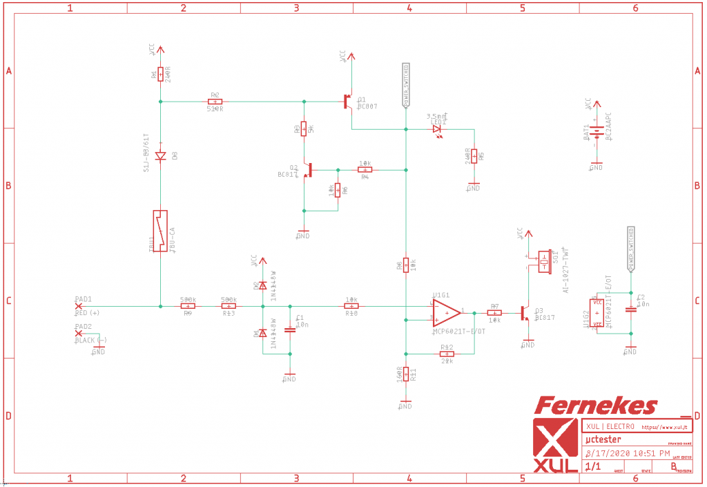
Schematics
Leo kindly provides a PDF of the schematics of the design which I captured as-is into EagleCAD. The only minor changes I did were to employ SMT-only packages, a single-opamp (MCP6021 in lieu of the MCP6022), and BC-series BJTs, just because I had these parts at hand.
A rough breakdown of the time spent on the schematics:
- 20% capturing
- 40% searching and checking options for some special parts (buzzer, batteries holder)
- 40% modeling new parts
In spite of its simplicity and that the design was given on a silver plate, I managed to commit a mistake by connecting the power rail of the opamp to VCC, instead of Q1’s collector (the main soft switch).
Obviously I realized it only after ordering the PCB for revision A 🙂
Debouncey
There’s one thing worth mentioning, which is the role of C1.
In the way it’s set up, it forms a low-pass filter to the input, with an approximate cutoff frequency of 15Hz. This prevents the opamp to rapidly strobe the buzzer with an annoying screechy sound when the input bounces around the triggering threshold.
Its value is a tradeoff between reaction times (the beep should come fast) and false re/triggering (so not that fast). I guess there are more convoluted ways to avoid the compromise (signalling as soon as possible and latch for a couple of milliseconds).
I’m not sure how Fluke multimeters continuity tests manage to have that amazingly fast reaction times with a perfect rejection to bounces and I guess that if there’s any possible way to improve this design might lay upon this feature.
Routing
Routing the board was really easy, given the low components count and ample surface.
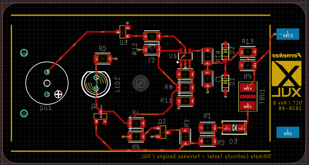
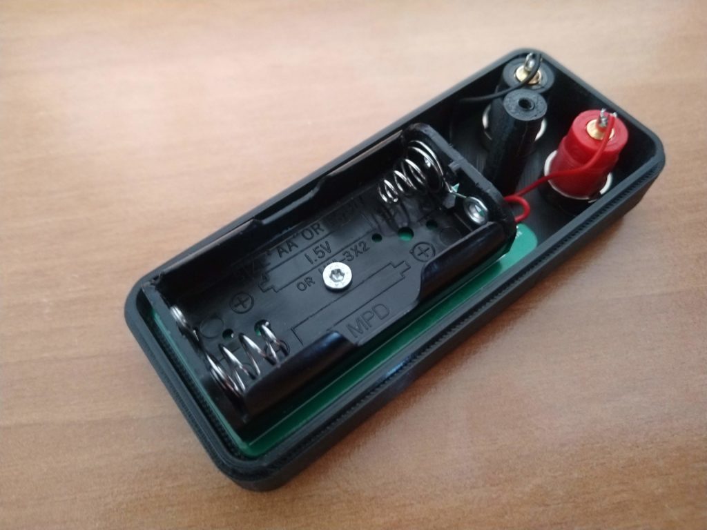
The size of the PCB has mainly been dictated by the batteries holder, which I decided to be soldered to the PCB instead of having it connected by lead wires.
Once the routing was done, I branched off a bit before committing its final dimensions and locations, and pushed the board to Fusion360.
Thinking ahead about an enclosure
At the moment (August 2020) an Autocad Eagle subscription entitles to Fusion360. I’m not sure what will be the future of these two products, since I have the impression Autocad will slowly phase out Eagle as a standalone product, focusing on its full integration into Fusion360.
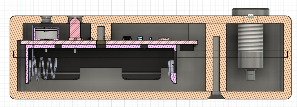
Pushing to Fusion from Eagle is a very simple process and given that the components in use have associated 3d models, the result is quite spectacular:
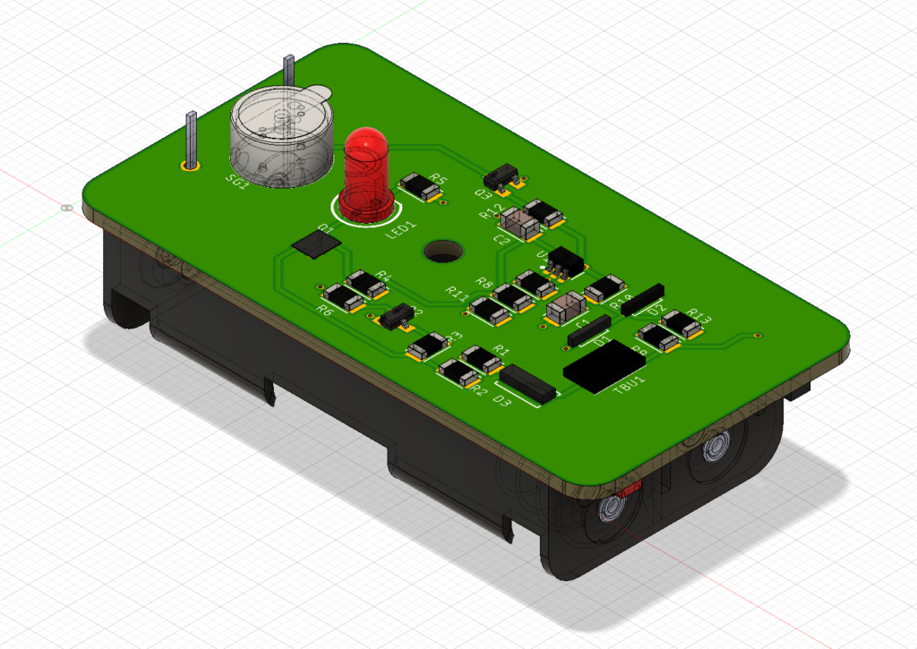
Once imported to Fusion, I was able to consider clearances, components locations, mounting options and how to expose the pads for the banana connectors in respect to an early idea of an enclosure.
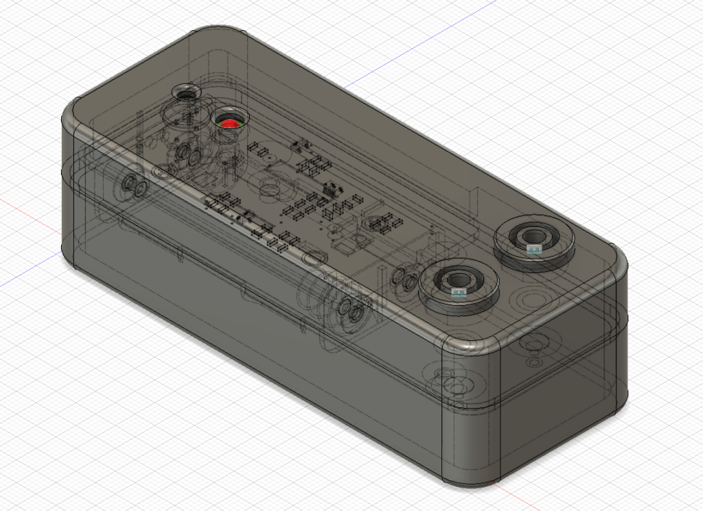
Far from being savvy about modeling, I chose an easy two-parts shell, which can be explored here.
By adding the connectors I was able to define the final sizes of the enclosure.
Other relevant features:
- LED and buzzer position (plus projected holes)
- PCB standoff and mounting point
- Shells coupling
LED and buzzer
These two components are exposed to the outside via holes.
On the first revision of the enclosure I modeled the buzzer hole a tad too little (1mm diameter). The buzzer is still audible but it’s quite muffled. The latest version has a bigger hole with a gentle fillet around both sides.
The LED could had been a bit more exposed, but I had to compromise with the length of the screw.
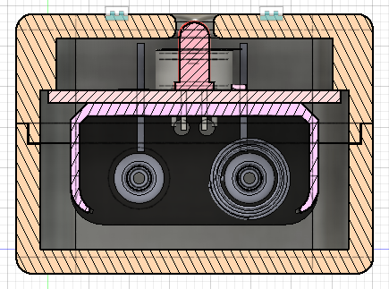
PCB standoff and mounting
The PCB lays on a rim which offers a lot of clearance and it’s firmly held in place by a standoff pillar and a 10mm self-driving screw.
The LED functions as registration point, keeping the PCB from rotating on the pillar’s axis.
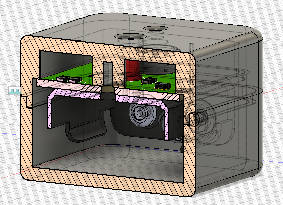
Shell coupling
I opted for a an alignment edge (is there a better term for it?) plus a single screw. The two work marvelously together, even if the screw is offset from the center.
As visible from the picture, the edge prevents rotation or shear, while the pillar couples the two parts together.
Initially I considered the option of embedding a nut or a threaded insert into the pillar. Having zero experience on materials and required clearances, I decided to go easy and to use the same hole pattern (and screw) planned to hold the PCB in place. Servicing the batteries should be done only once every lifetime anyway 🙂
The screws I used are 8x3mm self tapping, 90deg countersink, flat head.
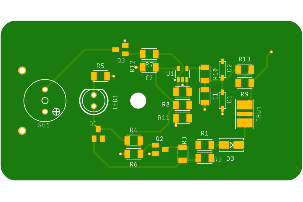
PCB assembly
I chose 1206 passives, given the low parts count and plenty of surface to waste.
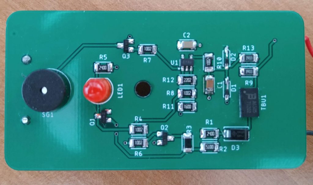
I had to solder the TBU with hot air, everything else required a mid-size soldering tip.
The two 1n4148 I had available were in a different package (SOD323 instead of SOD123) so I had to extend one side. The 390k resistors on the picture for R9/R13 as well are a temporary replacement of the 500k ones.
3D Printing
The enclosure has been sliced up with PrusaSlicer and printed with a Prusa MK3.
The two shells mated perfectly and the only thing I had to do was to de-burr the edges of the banana connectors (most likely they’ve got tapered).
As mentioned above, the only pending modification for a “final” print, would be the size of the buzzer’s port.
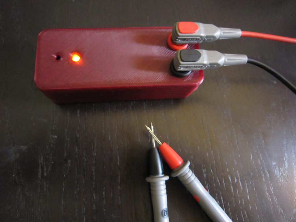
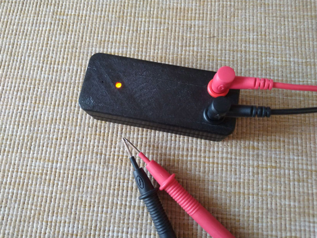
Testing and using it
I realized quite quickly that I was used to continuity testers with a high resistance threshold (Leo shows how a Fluke 87V beeps already at 50Ohm). By connecting a pair of probe leads I noticed that the tester beeps steadily with a firm contact of the two, but it gets flashy even by just sliding the two contacts together.
I was taken aback, but it’s actually true that imperfections of the surface and contaminants can cause sudden jumps in the conductive path. Most of the test leads are pointy and they’re able to penetrate dirt and sometime oxide layers.
I agree with Leo that real continuity is definitely not 50Ohm, but I haven’t had the chance for an extensive field test to prove that 5Ohm is an ideal threshold.
The nifty feature about the LED and buzzer being driven by two different thresholds is that one can still distinguish between low impedance and continuity and this accounts also for diode testing.
So, I’m sure I’m going to love this tool. It fits snugly in the hand and allows to clamp one of the leads along, even though it might be a nifty feature to add a magnet and/or a clip to the box.
Credits
Concept, idea, design is Leo’s, whom I thank for the instructional video and sharing. Check his great YouTube channel here.
Thanks for the support for the 3d printing to Johannes H.
And thanks to Uli F. for the modeling tips.
Files and downloads
- Eagle Schematics, board files, gerber and BOM can be found here
- Enclosure files can be viewed and downloaded here
Contributed pictures