After the Ultimate Continuity Tester article has been featured in Hackaday’s blog, and getting this question from github, I wondered whether there was a chance to simulate a mains power-cross event in order to provide quantitative argumentation as an answer.
The point here is: what happens if the tester is mistakenly connected to mains voltage?
A tentative approach would start by modeling the relevant parts of the circuitry that would be subjected to the negative swing of a mains cross-power event and by applying a constant voltage to the inputs.
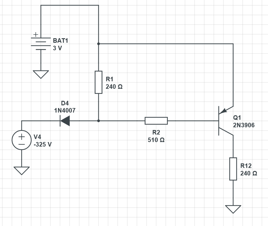
As Leo mentions, R1 would need to dissipate over 400W in such event and clearly it’s not the only component that would be releasing the magic smoke.
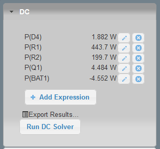
The simplest type of modeling for the current limiting that comes to mind is to replace the voltage source with a current source set to -75mA (for a TBU-CAxxx-050-WH, datasheet page 2). This should simulate the peak current and voltage that the parts have to endure:

The circuit above can be accessed here.
R1/R2 stress
Regarding voltage limits, the typical value is 150V-200V and it’s not of our concerns.
Power instead is relevant here, since we’re exceeding it.
A typical power rating for a 1206 resistor is 250mW. This value refers to the amount of power the component can safely dissipate into heat before reaching a damaging temperature and it also heavily depends on the component’s thermal resistance to the PCB and the ambient temperature (de-rating curves are also usually provided by the vendors).
When it comes to pulsing energy into the resistor, in this case exceeding by 2,5 times the nominal amount, how much is too much?
In our case we’re going to observe a protection event per cycle, when the voltage goes below 0V and the threshold current is exceeded. This means that the event happens 50 times in a second, for a duration of a microsecond.
We can calculate the average power by using this tool (well, pen and paper would work as well!):
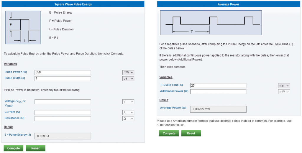
For simplicity, I’d consider a pulse of 659mW of 1uS, not considering the quiescent current upon which the TBU settles until it resets. This energy is pushed into R1 every 20ms, resulting in an average power of four orders of magnitude less than the maximum power rating of the resistor.
What if, as yngndrw asks, we use a TBU-CA085-100-WH, which triggers at 150mA?
R1’s peak power would go up to 2,5W, resulting in an average power of 0,125mW. Still chill 🙂
Q1 stress
For Q1 (actually in the circuit it’s a BC807) I hope it’s enough considering its relevant maximum ratings:
| Measurement | Max rating | With TBU-CAXXX-050 | With TBU-CAXXX-100 |
| Vcb | -50V | 1V | 1,26V |
| Vce | -45V | -39mV | -37mV |
| Veb | -5V | 1V | 1,34V |
| Ic | -1A (pulsed, 1ms) | -12mA | -12mA |
| Ib | -200mA (pulsed, 1ms) | -22mA | -46mA |
| Ptot | 250mW (safest) | 24mW | 60mW |
Therefore it seems that even the BJT might be able to comfortably survive with either TBU.